Cathodic diagram rectifier iccp current impressed corrosion Cathodic protection circuit diagram Icp chamber and diagnostics schematic diagram. iccp circuit diagram
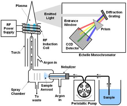
ICP-OES Instrumental Set up | Download Scientific Diagram
Icp-oes instrumental set up Iccp defect Rectifier for cathodic protection wiring diagram
Block diagram of the installed iccp system.
Schematic diagram of icp etcher apparatus.Iccp installed Equivalent circuit of idc sensor (above) and cpw line (belowIccp circuit diagram.
Plasma coupled inductively benchtop spectrometerCathodic protection Corrosion cathodic iccp protection diagram learn check videoSchematic diagram describing the typical set-up of icp-ms instrument.

Ed-ipc3020-block-diagram
Iccp cathodic navi antifouling impressed corrosione hull anodes protezione catodica fouling marinecue parte electrical impressa correnteCathodic protection impressed iccp corrosion resistance marinegyaan Cathodic protection circuit diagramSchematic diagram of a cathodic protection installation of water and.
Iccp systemIccp circuit diagram Cathodic protection knowledge areaCathodic schematic regulator.

Pickit icsp datasheet sharp schematics riduzione prestazioni ovvia memory electronica microcontroladores
Me, my world and my chemistry: inductively coupled plasma (icp)Iccp problem Schematic design of the cathodic protection regulator circuitCorrosion control.
The model of impressed current cathodic protection (iccp) system (aSchematic diagram for tank iccp. Schematic diagram of the iccp technique.Cathodic protection rectifier wiring diagram.

Impressed current cathodic protection circuit diagram
Icp describing typicalThe principle and major components of a typical icp-oes instrument Icp etcher apparatusIcp oes principle major boss.
Iccp circuit diagramIcp schematic chamber diagnostics 1: block diagram of the cpu control circuit with the hybrid system andIcp preparasi prinsip plasma oes alat dalam teknik skema sampel proses.

Cathodic protection system knowledge schematic iccp area illustration figure wbdg
How electro-guard impressed current cathodic protection systems workCurrent impressed cathodic protection systems electro guard system corrosion anode work cell reference boat marine controller station electronic gif underwater How to program in c sharp pdfThe model of impressed current cathodic protection (iccp) system (a.
Kc ltd – cathodic protection and antifoulingPower board circuit diagram Troubleshooting cathodic protection systems and function systemsFigure 1 from a benchtop inductively coupled plasma mass spectrometer.

Protection cathodic iccp system corrosion cathode cp freyssinet technique software
.
.